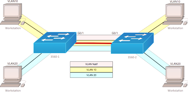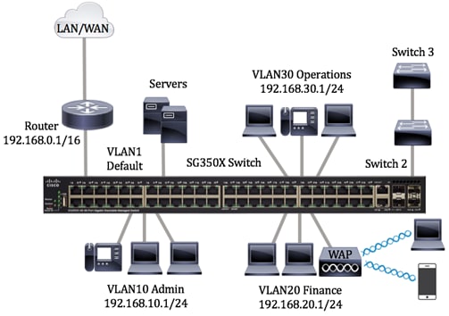

Both sides of the trunk link must be configured to be in same native VLAN. If a switch receives untagged Ethernet frames on its Trunk port, they are forwarded to the VLAN that is configured on the Switch as native VLAN. Through work I have access to an ESXi server the hardware is a bit dated, but it is version 6. GNS3 cant directly emulate switching hardware so you cannot create switches in the same way with an IOS image. Native VLAN on other side of the trunk link is different from what we configured here. Normally a Switch port configured as a trunk port send and receive IEEE 801.q VLAN tagged Ethernet frames. The recommended Cisco images to use with GNS3 are those from Cisco VIRL (IOSv, IOSvL2, IOS-XRv, ASAv). The CDP message "%CDP-4-NATIVE_VLAN_MISMATCH: Native VLAN mismatch discovered on FastEthernet0/24 (10), with 02 FastEthernet0/24 (1)." shows that the %CDP-4-NATIVE_VLAN_MISMATCH: Native VLAN mismatch discovered on FastEthernet0/24 (10), with 02 FastEthernet0/24 (1). 01(config-if)#switchport trunk native vlan 10 01>enableĮnter configuration commands, one per line.

In the example above we have a Ethernet 0/0 physical interface and two sub-interfaces: Ethernet 0/0.10 will be used for security zone INSIDE1 and. Each sub-interface will be configured for a VLAN, security zone and security level. To configure the trunk link, open console connection to Switch 1 and enter the commands as shown below. The physical interface on the ASA will become a trunk interface which is not assigned to any security zone. The above picture shows that the trunk link is connected to port fa0/24 on both switches.
Cisco asav change native vlan port how to#
Following example shows how to create and configure trunk link to carry multiple VLAN traffic and how to configure the native VLAN for a trunk link. By default, all switch ports in Layer 2 are configured to operate as access links.


 0 kommentar(er)
